Acknowledgement
We are very grateful to Mrs. Smita Adhikari for her valuable
suggestions, inspiration and full support for making it possible to perform a
brief case study on microprocessor based instrumentation system according to
the syllabus of Instrumentation-II and present this report within a short
period of time.
We are also grateful to the Electrical Department, PaschimanchalCampus
for providing us the recommendation letter subjected for visit to the industry.
We would like to thank Er. Ghanshyam Poudel from Kulekhani II for managing his
valuable time to show around the plant and providing information as per our
requirements.
We solely take the responsibility of any possible mistakes that may
have occurred in preparing this report and we would like to welcome comments
and queries during the presentation of this report.
Abstract
This report is prepared as per the visit for Case
Study based on microprocessor based instrumentation system included in the
syllabus of Instrumentation-II. This report includes brief introduction of
Khulekhani 2 Hydropower plant, detailed study of the instrumentation system
available at present in the Plant, and its characteristics. This report also
presents suitable alternatives and advancement to the existing instrumentation
system.
Like all production industries, Hydropower plant uses
a large number of instrumentation devices such as sensors, Mechanical equipment
and other electronic devices. These devices are synchronized very precisely so
as to meet the required flow of process. A single disturbance or error in a
system affects all the systems and devices connected together as well as other
instruments connected through that transmission line. That is why necessary
beforehand mechanisms and backup process are maintained to get through these
errors and maintain the stability and functioning of the whole power system.
We
studied the detail process and observe the possible changes that can enhance
the functioning and efficiency of the system. We also observed the process followed
in the global world and the improvement going in the Hydropower plant
around the globe. This report enrolls all the possible features that can be
implemented to this current system as per its hands on resources and other
technical difficulties.
Table of contents
Topics page
no.
1.
Introduction 1
1.1
Powerhouse
background 1
1.2
Salient features
2
2.
Current
process control system 2
2.1
Block
diagram 2
2.2
Features 3
2.2.1 Governor cabinet 3
2.2.2 Relay and recording Panel 6
2.2.3 Resistance Temperature Detector
(RTD) 6
2.2.4 Control room 7
2.3
Limitation 10
3.
Recommended
process control system 10
3.1
Block
Diagram 11
3.2
Features 11
3.3
Advantages
over existing system
14
4.
Recommendations 15
5.
Conclusion 15
6.
References 16
1.
INTRODUCTION
There is great potential of hydroelectricity in Nepal. According
to statistical record Nepal has potential of 83,000 MW hydroelectricity power
production. However, at present Nepal has produced only about 600 MW of
hydropower, which is not sufficient to meet the demand of whole country. Thus,
Nepal is facing serious attack of nearly 12 hours daily load shedding. This
directly affects the industrial field and overall development of the country.
The hydropower projects in Nepal are directly dependent on the
amount of water flowing in the river stream, so during dry season the power
production decreases significantly which results increase in duration of load
shedding. Among different hydropower models established in Nepal, Kulekhani is
only the hydropower project with reservoir. This type of hydropower can be the
permanent solution of the deep rooted load shedding.
The purpose of this research is to study about the technology that
are used in this hydropower for generation of the electricity, for controlling
the hardware equipment and manipulating the generated output electricity and
think about the new technology and equipment as well as the new manipulating
methods so that we can increase the production rate or to increase the
efficiency of the power house.
1.1
POWERHOUSE BACKGROUND
Kulekhani -2 Hydropower station,
located at Nibuwatar, Makwanpur, is a cascade of Kulekhani -1. Its installed
capacity is 32 MW having two units each of 16 MW. This powerhouse was designed
as peaking power station but it has been supporting as emergency stand by
station also. The annual expected energy generation capacity as primary energy
is 104.6 GWH. This project was constructed under the financial assistance of
Overseas Economic Cooperation Fund (OECF) of Japan and Government of Nepal at a
cost of NRs.124 million.
The main purpose for the
construction of this power station was to take the peak load only but the
unavailability of the sufficient power with respect to demand, the power
station was forced to operate as and when required.
1.2 Salient Features
Type :Cascade
of Kulekhani -1
Rated net head : 103.17 meter
Design discharge : 16.65 m3/s
Headrace tunnel : 4294 meter
Penstock pipe : 843 m long, 2.1 – 1.5m diameter steel pipe
Installed capacity : 32 MW
Turbine type and numbers : Pelton, 2 sets
Rated speed : 750 rpm
Type of generator : Vertical shaft, Synchronous
Capacity : 18.8 MVA
Rated voltage : 6.6 KV
Power transformer : 6.6/132KV, 1 phase, 12.6 MVA, 3 Nos
Average annual generation : 104.6 GWh
Commissioning date : 1986
Construction cost : NRs 124 million
Financed by :OECF and OPEC Fund
1.
Current
Process Control System
The
water from reservoir is carried through penstock to the turbine which is
controlled by hydraulic control (valves). There are two different turbines each
of 16 MW capacities. The generated power at 6.6 KV is stepped up through step
up transformer and is transmitted to Control Room. Control Room monitors and
controls the power generation, power distribution and control of turbine
through governor cabinet.
2.1 Block Diagram

2.2 FEATURES
2.2.1 GOVERNOR CABINET
A
governor is a combination of devices that monitor speed deviations in a
hydraulic turbine and converts that speed variation into a change of wicket
gate servomotor position which changes the wicket gate opening. This assembly
of devices would be known as a “governing system”. In a hydro plant this
system is simply called the “governor” or “governor equipment”. This wicket
gate opening which is responsible for the flow of water to the turbine thus
controls:
·
Flow of water through the Penstock
·
Alignment of the generator’s shaft unit
(vertical in the case of Kulekhani 2)
·
Power Production
GOVERNOR COMPONENTS
The main parts of the governor are
·
A speed sensing device,
usually a ball head
·
An oil pressure system,
hydraulic valves to control oil flow, and
·
One or more hydraulic
servomotors to move the wicket gates
·
Auxiliary Control
Speed Sensor: The ball head is the
component that responds to speed changes of the unit- the turbine. There are
various designs of ball heads, but generally, they consist of two flyweights
attached to arms that pivot near the axis of rotation. The arms are attached to
a collar on a shaft. As the ball head rotational speed increases, the flyballs
move out because of centrifugal force pushing a rod down. The rod, usually
termed the speeder rod, acts on the pilot valve to route oil to the main valve
and the servomotors. A decrease in speed will cause the valve to move upward, allowing
the servomotor to drain and move in the opening direction. As the servomotor
moves open, the valve is moved down by the speed droop lever, centering it over
the port and stopping the servomotor. The unit is now operating at a slightly
slower speed, but the servomotor will not overshoot because for a given speed
the servomotor must move to a specific position.
Oil
Pressure System: The oil pressure system consists of
oil pump/s, oil accumulator tank/s, oil sump, and the necessary valves, piping,
and filtering required.
Flow Distributing Valves: The
hydraulic system consists of an oil sump, one or two oil pumps, an air over oil
accumulator tank, and piping to the servomotors. Typically, there are two pumps
with lead and lag controls so that there is always a backup pump. Some systems
will share two pumps between two units so that in an emergency one pump could
be used for both units. The accumulator tank is usually sized so that in the
event the pumps fail, the gates can still be closed.
The size of the valve required to control the large amount of oil
flowing to the servomotors is too large to be controlled by the ball head.
Therefore, a hydraulic amplifier system is used. Oil is routed to a servo on
the larger valve by a small pilot valve. The pilot valve is very small so that
it is sensitive to the small forces that result from small changes in speed.
The larger valve may be called the main valve, regulating valve, control valve,
relay valve, or distributing valve. The pilot valve usually is designed with a
moveable bushing. The plunger of the pilot valve is connected, through a
floating lever, to the ball head, and the bushing is connected to main valve.
Whenever the pilot valve moves off center, oil is routed to the main valve
servo, causing the main valve to move. The pilot valve bushing is moved off
center by the main valve movement, blocking the port of the pilot valve,
stopping further main valve movement. The restoring lever between the main
valve and the pilot valve bushing is usually adjustable so that the ratio of
pilot valve movement to main valve movement is adjustable.
Auxiliary Control: Most
governor cabinets also have auxiliary controls that control the auxiliary
valves to control the gate position. Because of the relatively small ports of
the auxiliary valve, the gates are moved slowly and can be positioned
precisely. The auxiliary valve has no connection to the ball head, and
therefore, no speed control. Some of these auxiliary controls also react on the
alignment of the generator, that are based on the readings of the generator
guide bearings (upper and lower) and generator thrust bearings (that carry the
rotating weight of the rotor axis in the generator).
APPLICATION
It
is an important thing to understand that the government cabinet, as shown in
the figure, shows meters of various sensors such as speed meter, wattmeter,
etc. in analog calibration. These values will be seen by the person at site and
certain operations such as opening of valves, nozzle flows will be controlled.
2.2.2 RELAY AND RECORDING PANEL
This
unit is the statistical unit of the power house which takes electrical input
and gives mechanical change in flag as output. A protective
relay is an electromechanical
apparatus, often with more than one coil, designed to calculate operating
conditions on an electrical circuit and trip circuit breakers when a fault is
detected. Protection relays use arrays of induction disks, shaded-pole magnets,
operating and restraint coils, solenoid-type operators, telephone-relay
contacts, and phase-shifting networks. Protection relays respond to such
conditions as over-current, over-voltage, reverse power flow, over- and under-
frequency. Distance relays trip for faults up to a certain distance away from a
substation but not beyond that point. An important transmission line or
generator unit will have cubicles dedicated to protection, with many individual
electromechanical devices.
Relay panel includes relays such as overvoltage relay, over current relay, over
speed relay, percentage differential relay, time limiting relay, etc. These are
emf coils current signal trigger coils and signal coils that have directly
linked with recording panel. Recording panel includes over voltage for
generator circuit, over current for generator circuit, emergency stop, over
speed, etc. Flags trough which the operator manages the performances of power
house. The timely records of every hour are recorded through this panel. It
avoids malfunctioning and the performance of the power house elements.
2.2.3
RESISTANCE TEMPERATURE DETECTOR (RTD)
An
RTD is a device which contains an electrical resistance source which changes
resistance value depending on its temperature. This change of resistance with
temperature can be measured and used to determine the temperature of a process
or of a material. This principle based temperature measuring system was found
to measure the temperature of power house elements. As the temperature of power
house elements as stator, transformer, etc. changes the corresponding
resistance changes and can be seen on display.
2.2.4 CONTROL ROOM

Frequency control

VOLTAGE
CONTROL

• The exciter supplies the
field winding with direct current and thus comprises the “power part” of the
excitation system.
• The controller treats and
amplifies the input signals to a level and form that is suited for the control
of the exciter. Input signals are pure control signals as well as functions for
stabilizing the exciter system.
• The voltage measurement and
load compensation unit measures the terminal voltage of the generator and
rectifies and filters it. Further, load compensation can be implemented if the
voltage in a point apart from the generator terminals, such as in a fictional
point inside the generator’s transformer, should be kept constant.
• The power system stabilizer,
PSS, gives a signal that increases the damping to the controller. Usual
input signals for the PSS are deviations in rotor speed, accelerating power, or
voltage frequency.
• The limiter and protection can
contain a large number of functions that ensure that different physical and
thermal limits, which generator and exciter have, are not exceeded. Usual
functions are current limiters, over–excitation protection, and
under–excitation protection. Many of these ensure that the synchronous machine
does not produce or absorb reactive power outside of the limits it is designed
for.
2.3
LIMITATIONS
This hydropower project
was established in 1982, and there has not been improvements in technology
since then, so the limitations are basically due to the not implementing the
modern technology. The limitations that we found during our visit are listed
below:
Ø The
instrumentation system implemented in the powerhouse was open loop system i.e.
observation are made in control room and the manual commands are made
accordingly. The nozzle valve controls are controlled according to the load
power demand manually. The recording of powerhouse performance is noted
manually. Error handling and status signals are addressed by human operator.
This made the operation of power house dependent on manual work; we found this
as the main limitation of the power house.
Ø Large
use of mechanical switch instead of electronic switch.
Ø In
hydropower it uses all mechanical relays and flags and these are not replaced
by microprocessor based digital relays which have great precision and
maintenance capacity.
Ø The
commands form control room to power house was connected manually (through
phone), that should be connected electrically.
Ø The
machines used in the powerhouse are too old to use and are not updated
according to time.
3.
RECOMMENDED PROCESS CONTROL SYSTEM
3.1
BLOCK DIAGRAM

3.2 FEATURES
Programmable Logic Controller Concepts
Programmable
logic controller is basically a digital electronic apparatus; it has a
programmable memory for strong instructions to implement specific tasks for
control.
Advanced
PLCs are microprocessor based and can perform complex mathematical calculation
and function as well as logic, sequencing, timing and counting.
The
major components of a PLC are:
1. Processor
2. Input
Modules
3. Output
Modules
4. Programming
and Other Facilities
Component
Description:
Programmable
logic controllers typically contain a variable number of input/output (I/O)
ports and usually employ reduced instruction set computing (RISC), which
consists of simplified instructions that are intended to allow for faster
execution.
Input
Interface provides connection to the machine or process being controlled. The
principal function of the interface is to receive and convert field signals
into a form that can be used by the CPU.
CPU
provides the main intelligence in the PLC as is evident in every other system. The
output Interface takes signals from the processor and translates them into
forms that are appropriate to produce control actions by external devices.
General Concept:
A
hydropower operation will typically involve many operations and steps. Some of
these steps would occur in series and some would occur in parallel. Some events
may involve discrete setting of states in the plant like valves open or closed,
accessories on or off, and so on. With
help of PLC, use of hardwired relays is minimized. A large PLC has enough
number of relays to do all the operations. The advantages of these relays are
that these are
Digital,
so minimum damage to the system, cost reduction and less maintenance is
involved in their use. If there is any need to change the control system, only
the program is to be changed and it can be done easily without any cost
involvement.
In
continuous processes we may need to convert the analog signal to the acceptable
value to the PLC and then with A/D converter it is converted to digital input
to processor. A control algorithm is to be developed to get a control signal to
control the variable. There is always a set value to which the variable is
taken. By calculating the error, algorithm can be applied to get a control
signal. This control signal is then converted to analog signal and then
amplified to control the variable.
·
Automatic Start Sequence
·
Automatic Shutdown (Normal, Emergency).
·
Digital Governing using PLC
·
Speed Governing
·
Position Control
·
Protection System with PLC
·
Alarm and Annunciation using PLC
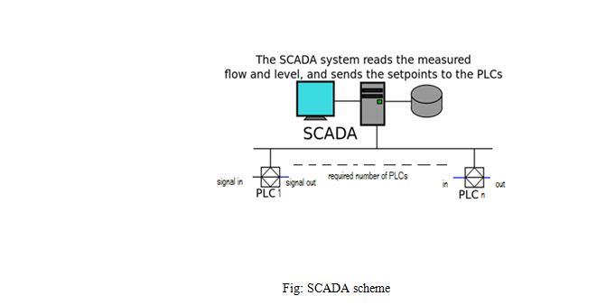
User Interfacing:
SCADA (Supervisory Control and Data
acquisition)/HMI concepts
Even though PLCs are responsible for automated control one needs
to keep an eye on all the processes taking place in the station and the house.
SCADA is a control system that is used for centralized monitoring and recording
of pumps, tank levels switches, etc. That is SCADA is there for supervision of
activities. Its components are:
·
A Human Machine Interface (HMI):
Monitor most commonly.
·
A computer system: used to
gather information and send control commands
·
RTU (Remote Terminal Units)/
PLC: connected to the physical equipments and convert actions to digital
signals. All major PLC manufacturers have offered integrated
HMI/SCADA system thus PLC are chosen above special purpose RTUs.
Visualization of plant status and condition, logging of events and
metering, and annunciation of alarm conditions are generally managed by the
station through HMI (Human Machine Interface). It serves as the local
operator’s portal into the process. The feedback control
loop passes through the RTU or PLC, while the SCADA system monitors the overall
performance of the loop.
In
this way, the operator can sit in his room and watch what goes on through the
plant and control the actions from there if required. But this isn’t the only
advantage the automation provides.
Some
of the pros are:
·
Increased system
availability and visibility
·
Decreased downtime
requirements to recover from a failure
·
Decreased cost in materials
and man hours for installation
·
Ease of control
1.3 ADVANTAGES
OVER EXISTING SYSTEM
Our purposed system consists of digital electronic devices which
are microprocessor based (PLC, SCADA).Thus this system is highly advantageous
over existing system.
Ø
One of the most important
improvements of our purposed system is that it provides automation.
Ø
It possesses centralized
monitoring and recording of pumps, tank levels switches +etc.
Ø
It is capable of performing complex
mathematical calculation and function as well as logic, sequencing, timing and
counting.
Ø
With help of PLC, use of hardwired
relays is minimized.
Ø Increased system availability and visibility.
Ø Decreased downtime requirements to recover from a failure.
Ø Decreased cost in materials and man hours for installation.
Ø Ease of control.
4.
RECOMMENDATIONS
v Implementation of electronic PLC over the mechanical governor
cabinet components.
v HMI over analogue meters i.e. a computerized user interface and
monitoring system over the analogue meters in the control room.
v Proper installation of a system as per the outlines mentioned in
our recommended system that uses PLC for controlled output and HMIs for
supervision.
5.
CONCLUSION
Thus, the visit to Kulekhani 2, provided us with the information
on power generation and system control. Though system is robust and reliable
the presence of local operator within the powerhouse is a necessity. This
manual supervision throughout the powerhouse requires numbers. This can be
improvised with the use of an automatic control system where supervision will
be done from the control room and the device itself will make necessary changes
to any unusual processing. Further these changes can be monitored and any
interruption can be performed from the control room. Lastly we gained lots of
information on hydro power generation and controlled instrumentation
implementation.
6.
REFERENCES
Ø
ASME,
The Guide to Hydropower Mechanical Design,1996
Ø
Nepal
Electricity Authority
Really informative report—appreciate how clearly it breaks down both the current instrumentation setup and potential upgrades for improved system reliability and efficiency. It’s fascinating to see how precision and backup systems play such a critical role in hydropower. On a related note, for those interested in exploring natural energy landscapes firsthand, Darjeeling offers a great blend of scenic beauty and hydropower relevance: https://northbengaltourism.com/darjeeling-tour-packages/
ReplyDelete